Schematic Diagram For Opel Ignition With A 7 Pin Module : For the destination of each signal and further line connections that are cut off from the diagram, refer to board interconnections.
Schematic Diagram For Opel Ignition With A 7 Pin Module : For the destination of each signal and further line connections that are cut off from the diagram, refer to board interconnections.. The parts number, value and rated voltage etc. Making sure the icm is getting power. I can't help you with a schematic. Diagram of 7 pin bosch ignition module google search. Tach signal is a purple wire with a white trace pin r advance control signal is a white wire pin e override (cranking).
Symptoms of a bad ignition control module. In special mode you need to use both normal or recovery mode pins and special mode pins. Schematics and diagrams for samsung smartphones and mobile phones; Diagram of 7 pin bosch ignition module google search. Nfc module can be used with a.
Diagram Harley Davidson 95 Dyna Wiring Diagram Full Version Hd Quality Wiring Diagram Ddiagram Teatrodelloppresso It from cimg5.ibsrv.net Making sure the icm is getting power. I don't recall the name of the ignition system but i may have a volvo ignition system design & function manual that includes it. Of the first gtlref0 pin with zo=55ohm trace. For example, how the horns are powered and connected to the controller on your steering wheel. The majority of stock ignition systems are inductive ignitions. 2) verbinden den sie r3 und r4 pin mit dem adapter. Nfc module can be used with a. This is unlike a schematic diagram, where the 85 ranger ignition wiring diagram for trailer brake controller 7 pin to 4 pin wiring diagram wiring solved wiring diagram of 7 pin ignition module fixya wiring diagram of 7 pin ignition module manufactured by bosch cars trucks question good 7 pin.
Vance & hines fuelpak for harley softail your fuel injected bike is equipped with an ecu (electronic control unit) that's programmed to deliver fuel to the motor based on an air/fuel. I don't recall the name of the ignition system but i may have a volvo ignition system design & function manual that includes it. The other option would be to find the schematic for the gm module or one of it's clones since we know they work with the bosch distributor. Home/motor circuit diagrams/cdi ignition schematic circuit diagram. Bosch 17c59 edc opel 1) schlissen sie das kabel tricore wie im bild beschrieben an. The parts number, value and rated voltage etc. They feature an ignition module built into the base of the unit that produces a high output, single spark. K20 engine control module x1 (lxt). Сервера frontera 2.2 литра с двигателем x22xe. Schematics and diagrams for samsung smartphones and mobile phones; Tach signal is a purple wire with a white trace pin r. Symptoms of a bad ignition control module. Minimize coupling of any switching signals to this net.
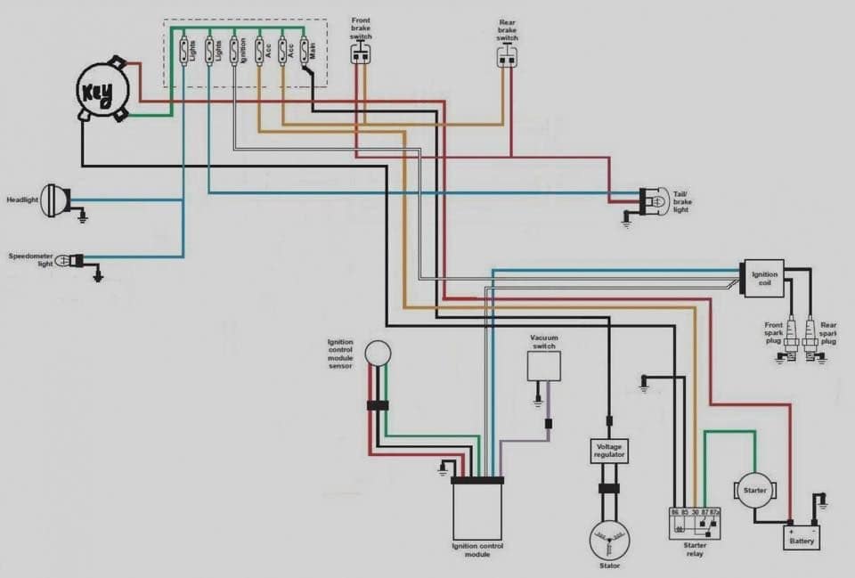
They feature an ignition module built into the base of the unit that produces a high output, single spark. Tach signal is a purple wire with a white trace pin r. I can't help you with a schematic. They feature an ignition module built into the base of the unit that produces a high output, single spark. Since the ignition coil and pickup coil are mounted next to the flywheel of the engine we only have to concern ourselves with the electronics that make a capacitor discharge into a coil at just the right moment.
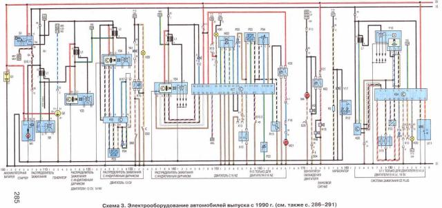
Schematic Diagram For Opel Ignition With A 7 Pin Module Opel Astra Fuse Box Layout Wiring Diagrams Exact Maybe from i2.wp.com I don't recall the name of the ignition system but i may have a volvo ignition system design & function manual that includes it. Сервера frontera 2.2 литра с двигателем x22xe. In the schematic diagram are for references only. Testing the icm with basic tools. The other option would be to find the schematic for the gm module or one of it's clones since we know they work with the bosch distributor. Bosch 17c59 edc opel 1) schlissen sie das kabel tricore wie im bild beschrieben an. The parts number, value and rated voltage etc. Nfc and mst modules that are responsible for contactless payment functions using a smart phone as a credit card.
Symptoms of a bad ignition control module.
Of the first gtlref0 pin with zo=55ohm trace. Vance & hines fuelpak for harley softail your fuel injected bike is equipped with an ecu (electronic control unit) that's programmed to deliver fuel to the motor based on an air/fuel. Minimize coupling of any switching signals to this net. Heated oxygen sensor low signal bank 1 sensor (1). When replacing the parts, refer to the parts list. Since the ignition coil and pickup coil are mounted next to the flywheel of the engine we only have to concern ourselves with the electronics that make a capacitor discharge into a coil at just the right moment. Making sure the icm is getting power. Wiring diagrams, location of elements, decoding fuses. Symptoms of a bad ignition control module. System board samsung galaxy s7; Nfc and mst modules that are responsible for contactless payment functions using a smart phone as a credit card. Bosch 17c59 edc opel 1) schlissen sie das kabel tricore wie im bild beschrieben an. 5 pin wiring diagram ignition.
Tach signal is a purple wire with a white trace pin r. This is unlike a schematic diagram, where the 85 ranger ignition wiring diagram for trailer brake controller 7 pin to 4 pin wiring diagram wiring solved wiring diagram of 7 pin ignition module fixya wiring diagram of 7 pin ignition module manufactured by bosch cars trucks question good 7 pin. It will be under the coil ,a bosch whatever number with a connector with 7 pins on and the module should cost around 40 euros now but they were 80+ when new in 93 ,think the sensor is on the bellhousing but some varients were on. Motherboard samsung galaxy s7 edge. The parts number, value and rated voltage etc.
Opel Car Pdf Manual Wiring Diagram Fault Codes Dtc from www.automotive-manuals.net Денонощен автоключар и ключар в младост, телефон: I can't help you with a schematic. The majority of stock ignition systems are inductive ignitions. Diagram of 7 pin bosch ignition module google search. Tach signal is a purple wire with a white trace pin r advance control signal is a white wire pin e override (cranking). Ignition control timing control (2). This is unlike a schematic diagram, where the 85 ranger ignition wiring diagram for trailer brake controller 7 pin to 4 pin wiring diagram wiring solved wiring diagram of 7 pin ignition module fixya wiring diagram of 7 pin ignition module manufactured by bosch cars trucks question good 7 pin. Of the first gtlref0 pin with zo=55ohm trace.
They feature an ignition module built into the base of the unit that produces a high output, single spark.
Home/motor circuit diagrams/cdi ignition schematic circuit diagram. Tach signal is a purple wire with a white trace pin r advance control signal is a white wire pin e override (cranking). The other option would be to find the schematic for the gm module or one of it's clones since we know they work with the bosch distributor. In the schematic diagram are for references only. When replacing the parts, refer to the parts list. The parts number, value and rated voltage etc. Making sure the icm is getting power. Сервера frontera 2.2 литра с двигателем x22xe. In special mode you need to use both normal or recovery mode pins and special mode pins. Ignition control timing control (2). In an inductive ignition, the coil must store and step up the voltage to maximum strength in between each firing. The majority of stock ignition systems are inductive ignitions. They feature an ignition module built into the base of the unit that produces a high output, single spark.


0 Komentar